Serialisation

Serialise all rigid bodies to JSON, for import into external software such as Unreal, Unity, Godot, CryEngine or any other engine able to read and parse JSON, including your own custom game engine.
Units
- All linear units are in
centimeters - All angular units are in
radians - All quaternions are ordered
XYZW
Overview
On playback, Ragdoll generates a physical representation of your Maya scene, suitable for simulation. You can gain access to that representation, independent of Maya, for use in your own software and for your own purposes.
This enables you to use Maya as an authoring environment for general-purpose physics scenes, including full or partial ragdolls, for characters or props and even full environments.
Target Audience
- Game programmers working on a custom engine
- Technical Directors working with e.g. Unreal Engine, Unity or CryEngine
- Roboticists exploring algorithms on humanoids with rigid bodies
- Scientists in Machine Learning in need of bespoke ragdolls for their work
Usecases
Once a ragdoll has been authored in Maya, it can be exported for later import into external software for a variety of purposes.
- Game Development where main or secondary characters need a physics representation
- Virtual Production where you need Motion Builder or Unreal Engine to reproduce physics happening in Maya for real-time feedback
- Robotics where you want interactive control over parameters that are also applied to a physical real-world equivalent, like Boston Dynamics's Atlas
- Reinforcement Learning where algorithm and articulation depend on each other and are iterated upon in parallel, like OpenAI's gym environments and algorithms
- Debugging in cases where odd things happen and you just require deep insight into what the solver sees
Concepts
Ragdoll internally stores data as "entities" and "components".
- Entity is a unique identifier for any "thing" in the solver, like a rigid body, a constraint or force.
- Component is a set of data, like the transformation or rigid body properties, associated to an entity
The exported format reflects this relationship and looks something like this.
{
  "entities": {
    "10": {
      "components": {
        "NameComponent": "upperArm",
        "ColorComponent": [1.0, 0.0, 0.0],
        "GeometryDescriptionComponent": "Capsule",
        ...
      }
    },
    "15": {
      "components": {
        "NameComponent": "lowerArm",
        "ColorComponent": [0.0, 1.0, 0.0],
        "GeometryDescriptionComponent": "Box",
        ...
      }
  }
}
Rigid Body
A single translation/rotation pair.
Components
| Component | Description |
|---|---|
NameComponent |
Name and path in Maya |
ColorComponent |
Used in Maya viewport |
SceneComponent |
Reference to the scene entity this rigid belongs to |
RestComponent |
Initial transformation |
RigidComponent |
Physics attributes |
GeometryDescriptionComponent |
Shape attributes |
"RigidComponent": {
  "type": "RigidComponent",
  "members": {
    "enabled": true,
    "mass": 1.0,
    "friction": 0.80,
    "restitution": 0.10,
    "thickness": 0.0,
    "disableGravity": false,
    "collide": true,
    "kinematic": false,
    "dynamic": true,
    "sleeping": false,
    "linearDamping": 0.5,
    "angularDamping": 1.0,
    "positionIterations": 8,
    "velocityIterations": 1,
    "maxContactImpulse": -1.0,
    "maxDepenetrationVelocity": -1.0,
    "sleepThreshold": 0.00,
    "enableCCD": false,

    # A value of -1 means "automatically computed"
    "angularMass": {
      "type": "Vector3",
      "values": [-1.0, -1.0, -1.0]
    },

    # A value of 0 means "automatically computed"
    "centerOfMass": {
      "type": "Vector3",
      "values": [0.0, 0.0, 0.0]
    }
  }
}
Shape
Every rigid has exactly one collision shape. The transformation of this shape can be optionally offset, and that offset happens in the frame of the rigid.
    ________
 ^ |\       \
 | | \_______\
 | |  |      |
 o--\-|->    |
  \  \|______|
   \
    v
In this example, the center of the box is offset from the center of the rigid along the X axis. Notice how the geometry is relative the axis of the rigid, so rotating the rigid along the Z axis would naturally take the geometry with it.
"GeometryDescriptionComponent": {
  "type": "GeometryDescriptionComponent",
  "members": {
    "type": "Capsule",

    # Used by Capsule
    "length": 0.123,

    # Used by Sphere
    "radius": 0.012,

    # Used by Box
    "extents": {
      "type": "Vector3",
      "values": [0.123, 0.024, 0.0247]
    },

    # Translation relative the associated rigid
    "offset": {
      "type": "Vector3",
      "values": [0.033, -0.05, 0.00]
    },

    # Rotation relative the associated rigid
    # Ordered as XYZW
    "rotation": {
      "type": "Quaternion",
      "values": [0.87, -0.47, 0.00, 0.00]
    }
  }
}
Constraint
A relationship between two rigid bodies is referred to as a "constraint". A constraint constrains the way two rigid bodies move relative each other.
For example, the position of the lower arm is typically associated with the tip of the upper arm. Wherever the upper arm goes, the lower arm must follow. It may also be further limited in how it is oriented, to e.g. prevent a lower arm from bending past the natural elbow limit; i.e. to rotate between 20-180 degrees along the Z axis, and 0-10 degrees around the X and Y axis (as that rotation would normally come from twisting the upper arm).
- All constraints are bi-directional
- Rigid A attaches to B, as B attaches to A
- The point on A where B attaches is referred to as the
parentFrame - The point on B where A attaches is referred to as the
childFrame
Despite the name, there is no notion of hierarchy or "parent" in Ragdoll; the naming reflects the hierarchy as represented in Maya, where constraints are parented to the rigid representing the childFrame.
Components
| Component | Description |
|---|---|
JointComponent |
References to associated rigids and frame matrices |
LimitComponent |
Optional limits on translation and/or rotation |
DriveComponent |
Optional target transformation, i.e. the animation |
"JointComponent": {
  "type": "JointComponent",
  "members": {

    # Reference to the associated rigid body entities
    "parent": 1048586,
    "child": 1048584,

    # The translate/rotate of the parent
    # rigid in the frame of child rigid
    "parentFrame": {
      "type": "Matrix44",
      "values": [
        0.760, -0.594, -0.259, 0.0,
        -0.648, -0.680, -0.340, 0.0,
        0.0262, 0.4274, -0.903, 0.0,
        10.51, -0.646, 0.0, 1.0
      ]
    },

    # The translate/rotate of the child
    # rigid in the frame of parent rigid
    "childFrame": {
      "type": "Matrix44",
      "values": [
        0.606, -0.751, -0.259, 0.0,
        -0.785, -0.515, -0.340, 0.0,
        0.122, 0.4103, -0.903, 0.0,
        0.0, 0.0, 0.0, 1.0
      ]
    },

    # Allow intersections between connected rigids
    "disableCollision": true
  }
}
Limit
Constraints may optionally have a "limit", which means it can keep a rigid within a given angle ("angular limit") or position ("linear limit").
Min & Max
Values represent a upper end of a range. With x=5 the minimum value of the linear X axis is -5.
"LimitComponent": {
  "type": "LimitComponent",
  "members": {
    "enabled": true,
    "x": -1.0,           # Linear limit along the X-axis
    "y": -1.0,
    "z": -1.0,
    "twist": 0.78,       # Angular limit along the X-axis
    "swing1": 0.78,      # ..Y
    "swing2": 0.78,      # ..Z
    "angularStiffness": 1000000.0,
    "angularDamping": 10000.0,
    "linearStiffness": 1000000.0,
    "linearDamping": 10000.0
  }
}
Locked, Free or Limited
A value of -1 means the axis is "Locked", i.e. the value along this axis cannot change. A Point Constraint is typically locked on all linear axes, but free on the angular axes. A value of 0 means the axis if "Free", meaning it has no effect. It is "limitless". A value above 0 indicates the range of a given limit.
<0means Locked=0means Free>0means Limited
Drive
A constraint may optionally have a "drive", which means having one rigid reach a target position and/or angle relative another rigid. The typical use case is having simulation match your input animation, where the animation provides the positions and angles.
"DriveComponent": {
  "type": "DriveComponent",
  "members": {
    "enabled": true,
    "linearStiffness": 0.0,
    "linearDamping": 0.0,
    "angularStiffness": 10000.0,
    "angularDamping": 1000.0,
    "acceleration": true,
    "target": {
      "type": "Matrix44",
      "values": [
        0.973, 0.2267, 0.0, 0.0,
        -0.226, 0.973, 0.0, 0.0,
        0.0, 0.0, 0.999, 0.0,
        0.1051, -0.006, 0.0, 1.0
      ]
    }
  }
}
Data Types
In addition to the plain-old-data types int, double and bool, these are all possible data types found in the exported JSON.
{
  "type": "Color4",
  "values": [
    0.4429999887943268,  # red
    0.7049999833106995,  # green
    0.9520000219345093   # blue
    1.0                  # alpha
  ]
}

{
  "type": "Vector3",
  "values": [
    100.00001788139201,  # x
    100.00001788139201,  # y
    100.00000000000003   # z
  ]
}

{
  "type": "Quaternion",
  "values": [
    0.8791841887437938,     # x
    -0.47648206919348187,   # y
    -2.7953360940182678e-8, # z
    1.191501461145112e-7    # w
  ]
}

{
  # Unscaled, unsheared matrix
  "type": "Matrix44",
  "values": [
    1.0, # rotation matrix
    0.0, # rotation matrix
    0.0, # rotation matrix
    0.0,
    0.0, # rotation matrix
    1.0, # rotation matrix
    0.0, # rotation matrix
    0.0,
    0.0, # rotation matrix
    0.0, # rotation matrix
    1.0, # rotation matrix
    0.0,
    0.0, # translateX
    0.0, # translateY
    0.0, # translateZ
    1.0
  ]
}
Reference
Components
These are all possible types of components found in the exported JSON.
SolverComponentSceneComponentNameComponentColorComponentRestComponentScaleComponentRigidComponentGeometryDescriptionComponentJointComponentDriveComponentLimitComponentConstraintUIComponentRigidUIComponentDriveUIComponentLimitUIComponent
Output Example
Here's an example of what a complete dump looks like.
Code Example
Test your dump, by re-building the scene in Maya.
from maya import cmds
from ragdoll.vendor import cmdx


class Component(dict):
    """Simplified access to component members"""
    def __getattr__(self, key):
        value = self["members"][key]

        if not isinstance(value, dict):
            return value

        if value["type"] == "Vector3":
            return cmdx.Vector(value["values"])

        elif value["type"] == "Color4":
            return cmdx.Color(value["values"])

        elif value["type"] == "Matrix44":
            return cmdx.Matrix4(value["values"])

        elif value["type"] == "Quaternion":
            return cmdx.Quaternion(*value["values"])

        else:
            raise TypeError("Unsupported type: %s" % value)


def dedump(dump):
    with cmdx.DagModifier() as mod:
        root = mod.createNode("transform", name="dump")

    for entity, data in dump["entities"].items():
        comps = data["components"]

        if "RigidComponent" not in comps:
            continue

        name = Component(comps["NameComponent"])

        if not name.path:
            # Bad export
            continue

        joint = name.path.rsplit("|", 3)[-2]

        scale = Component(comps["ScaleComponent"])
        rest = Component(comps["RestComponent"])
        desc = Component(comps["GeometryDescriptionComponent"])

        # Establish rigid transformation
        tm = cmdx.TransformationMatrix(rest.matrix)

        # Establish shape
        if desc.type in ("Cylinder", "Capsule"):
            radius = desc.radius * scale.absolute.x
            length = desc.length * scale.absolute.y
            geo, _ = cmds.polyCylinder(axis=(1, 0, 0),
                                       radius=radius,
                                       height=length,
                                       roundCap=True,
                                       subdivisionsCaps=5)

        elif desc.type == "Box":
            extents = desc.extents
            extents.x *= scale.absolute.x
            extents.y *= scale.absolute.y
            extents.z *= scale.absolute.z
            geo, _ = cmds.polyCube(width=extents.x,
                                   height=extents.y,
                                   depth=extents.z)

        elif desc.type == "Sphere":
            radius = desc.radius * scale.absolute.x
            geo, _ = cmds.polySphere(radius=radius)

        else:
            print("Unsupported shape type: %s.type=%s" % (name.path, desc.type))
            continue

        with cmdx.DagModifier() as mod:
            transform = mod.createNode("transform", name=joint, parent=root)
            transform["translate"] = tm.translation()
            transform["rotate"] = tm.rotation()

        # Establish shape transformation
        offset = desc.offset
        offset.x *= scale.absolute.x
        offset.y *= scale.absolute.y
        offset.z *= scale.absolute.z

        geo = cmdx.encode(geo)
        geo["translate"] = offset
        geo["rotate"] = desc.rotation

        transform.addChild(geo)


# Usage Example
import json
dump = cmds.ragdollDump()
dump = json.loads(dump)
dedump(dump)
More Examples
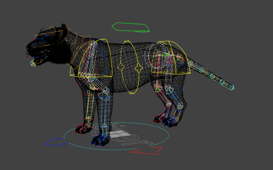
Tiger
Courtesy of www.cgspectrum.com
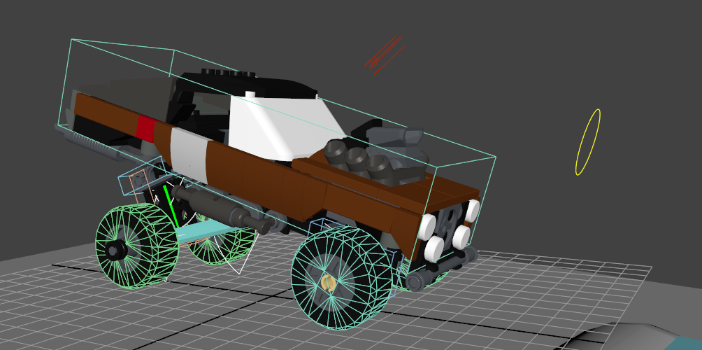
Ragcar
Model from https://mecabricks.com
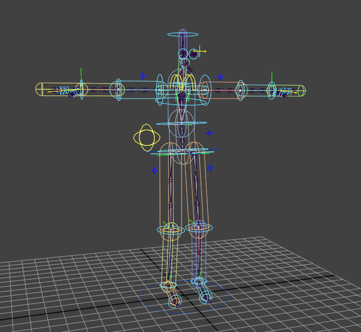
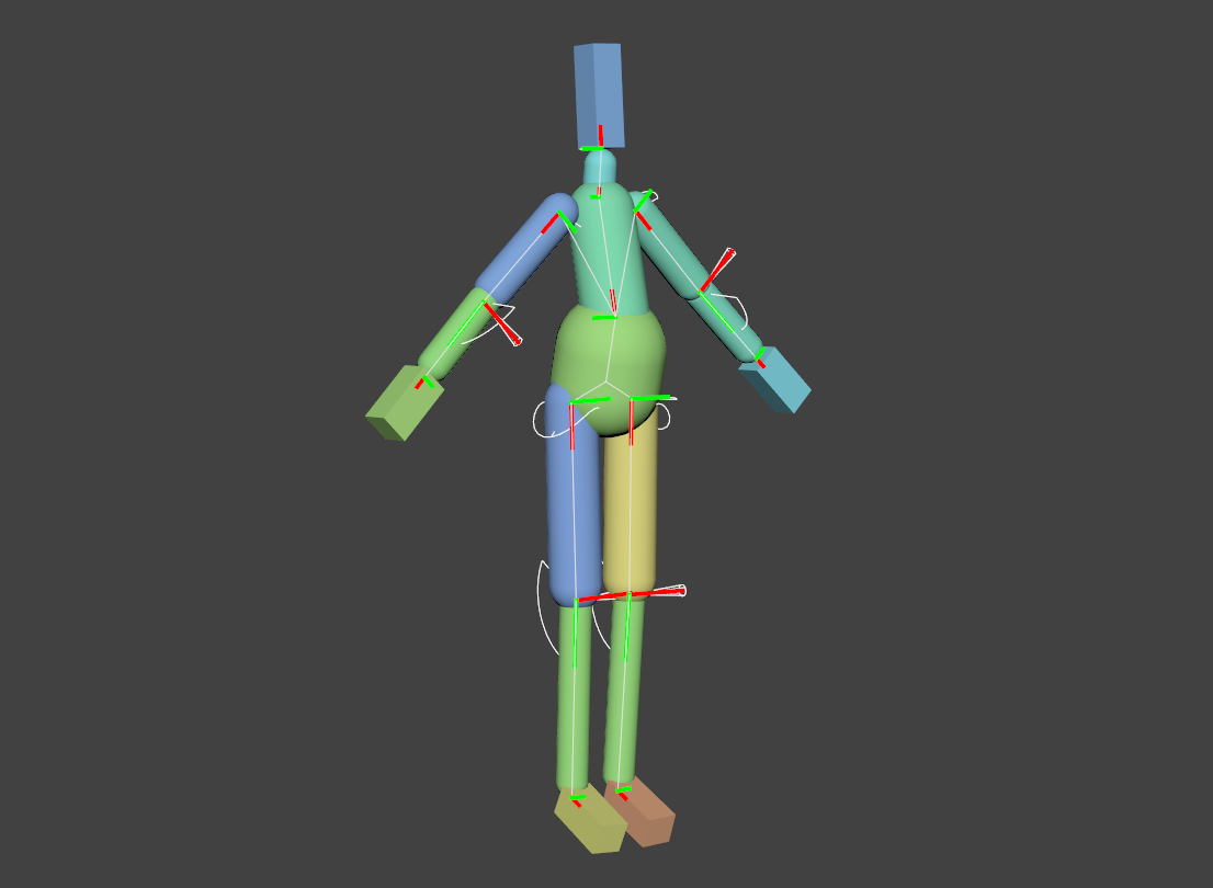
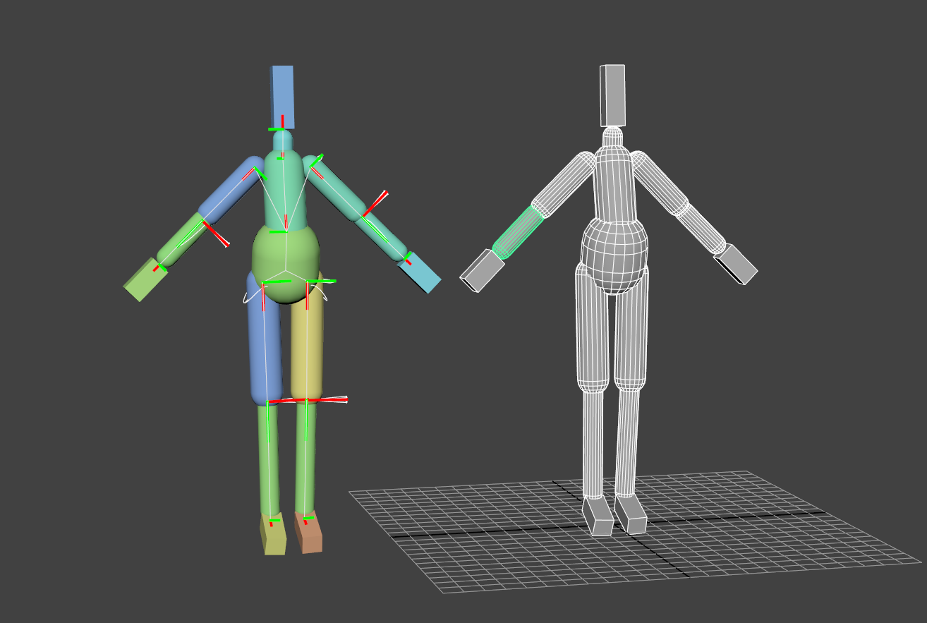
Advanced Skeleton
A generic human character, rigged with AS.